The Installation Variables That Make or Break an NFC Reader Deployment
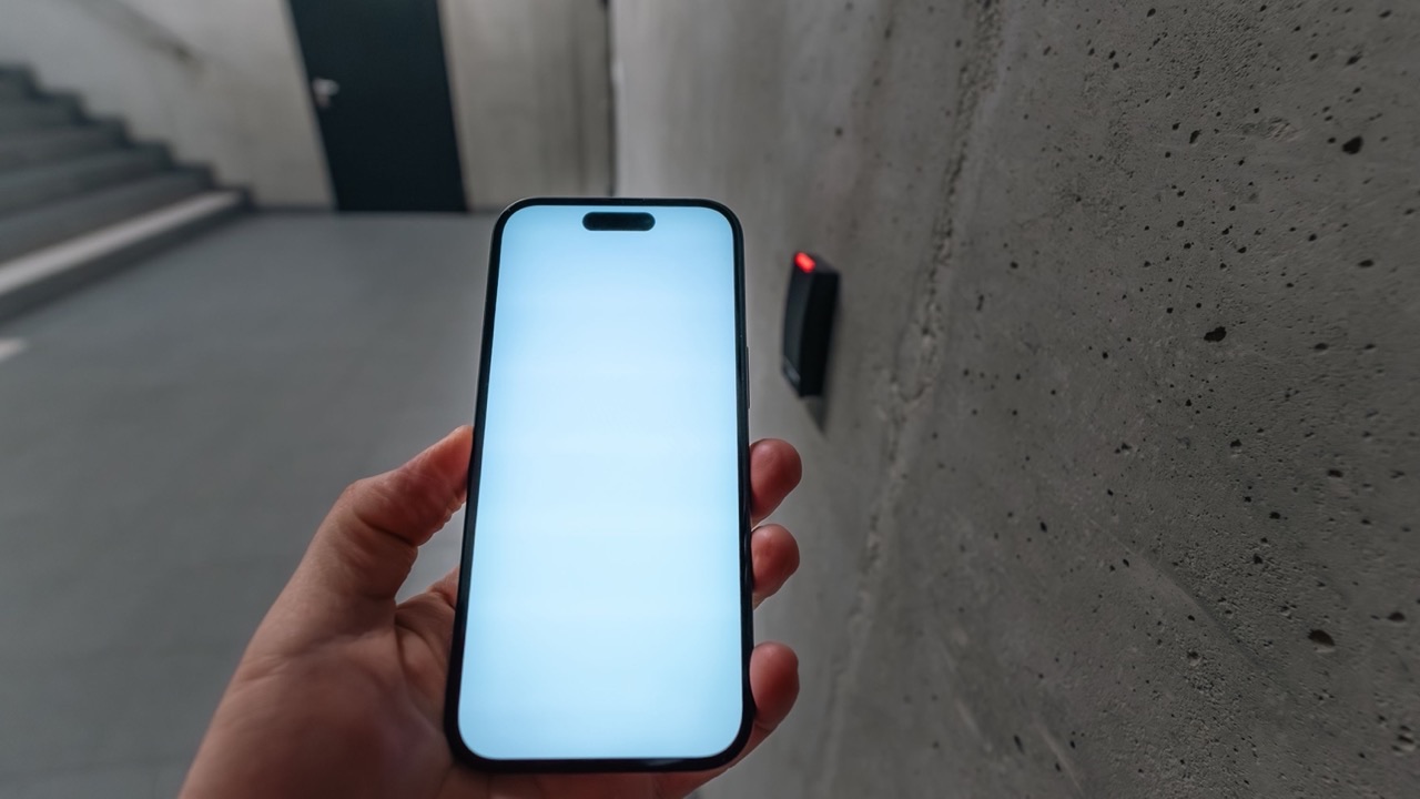
NFC reader performance specs are measured in a test fixture: antenna facing up, tag placed at the center, no surrounding metal, controlled temperature. The read range listed on a datasheet reflects that environment. What happens when the same reader goes into an access control panel in a metal door frame, a retail kiosk with a steel enclosure, or a wall-mounted terminal next to a HVAC duct is a different matter entirely. The gap between datasheet performance and real-world performance is almost always explained by installation variables, not by the hardware.
Understanding which variables matter — and by how much — is what determines whether an NFC reader deployment works reliably from day one or requires troubleshooting after installation.
Metal surfaces and the field distortion problem
NFC operates at 13.56 MHz using inductive coupling — the reader generates a magnetic field, and the tag’s antenna coil couples to that field to receive power and exchange data. Magnetic fields at this frequency interact strongly with conductive materials. When metal is placed close to the reader antenna, it creates eddy currents that oppose the reader’s field, effectively reducing the field strength available for coupling with the tag.
The practical effect is range reduction. A reader with a 10cm read range in free space may drop to 3–4cm when mounted flush against a steel surface. In some cases, the field distortion is severe enough to prevent communication entirely at any distance.
Two approaches address this. First, ferrite sheet material can be placed between the reader antenna and the metal surface. Ferrite guides the magnetic flux and prevents the metal from shorting the field. Most purpose-built embedded NFC antennas intended for device integration include ferrite backing for this reason. Second, physical standoff between the reader antenna and the metal surface — typically 5–10mm minimum — reduces the eddy current effect. Readers mounted with a plastic spacer or recessed in a non-metallic housing perform significantly better than those mounted directly on metal.
In access control installations, the reader’s position within the door frame matters. A reader mounted at the edge of a metal frame behaves differently from one centered in a plastic housing embedded in the wall. Specifying reader housing material and standoff geometry is part of the installation design, not just the product selection.
Adjacent antenna interference in multi-reader installations
When multiple NFC readers are installed in close proximity — a turnstile bank, a multi-door access corridor, a retail checkout lane with several terminals — the readers can interfere with each other. At 13.56 MHz, the magnetic field of one reader extends beyond its intended read zone and can activate tags intended for an adjacent reader, or desensitize a reader by placing it in the field of its neighbor.
The interference is proportional to the field strength of each reader and inversely proportional to the distance between them. Readers operating at maximum power are more likely to interfere with adjacent units than readers tuned to the minimum power required for reliable operation at the intended range. This is why reader power settings should be configured for the actual installation rather than left at factory defaults — factory defaults assume a standalone installation.
Physical separation is the most reliable solution. At 13.56 MHz, the field falls off steeply with distance; doubling the separation between reader antennas reduces cross-coupling substantially. Where physical separation isn’t possible, alternating the reader activation timing (anti-collision protocols that stagger reader poll cycles) can reduce simultaneous field overlap, though this adds software complexity and may introduce read latency.
Cable length and its effect on antenna tuning
NFC reader antennas that connect to a reader module via cable are part of a tuned circuit. The antenna, the matching network, and the cable together determine the resonant frequency of the system. Cable length affects the impedance the reader sees at the antenna connection point. Changing the cable length — even by 10–20cm — can detune the circuit enough to reduce read range and reliability.
This matters most in installations where the reader PCB is located at a distance from the antenna, such as a kiosk where the reader board is in an equipment bay and the antenna is at the user interface. If the cable length was not accounted for in the antenna matching design, the as-installed performance will differ from the benchtop performance. Specifying cable length at the antenna design stage and avoiding field modifications that change the cable run is important for maintaining the tuned circuit integrity.
Temperature and its effect on resonant frequency
The resonant frequency of an NFC antenna shifts with temperature. Component values in the matching network — capacitors in particular — have temperature coefficients that cause the antenna’s resonant frequency to drift as the ambient temperature changes. An antenna tuned precisely at 13.56 MHz at 25°C may be off-resonance by several hundred kHz at -10°C or +50°C.
For indoor installations with stable ambient temperature, this is rarely a significant problem. For outdoor access control readers, industrial readers in cold storage facilities, or readers in environments with wide diurnal temperature variation, thermal drift of the resonant frequency contributes to inconsistent performance — good reads in summer, marginal reads in winter, without any other change to the installation.
Matching network components with low temperature coefficients (C0G/NP0 capacitors rather than X7R or Y5V) reduce this effect. It’s a component-level specification choice that doesn’t appear in most reader product descriptions but matters for installations in thermally variable environments.
What a reliable NFC reader deployment actually requires
The installation design for a reliable NFC reader deployment needs to address each of these variables explicitly. Metal surface proximity determines whether ferrite backing or standoff spacing is required. Reader density determines whether power levels need to be reduced or read timing needs to be staggered. Cable routing needs to be fixed in the antenna design rather than left to field discretion. And environmental temperature range needs to inform the component selection in the matching network.
A NFC reader antenna that’s correctly specified for its installation environment will perform close to its free-space specification. One installed without accounting for these variables will underperform in ways that are frustrating to diagnose after the fact, because the hardware will test correctly on the bench while failing intermittently in the field.
The datasheet range is achievable. Whether it’s achieved depends on what surrounds the antenna after it’s installed.